


Final Project
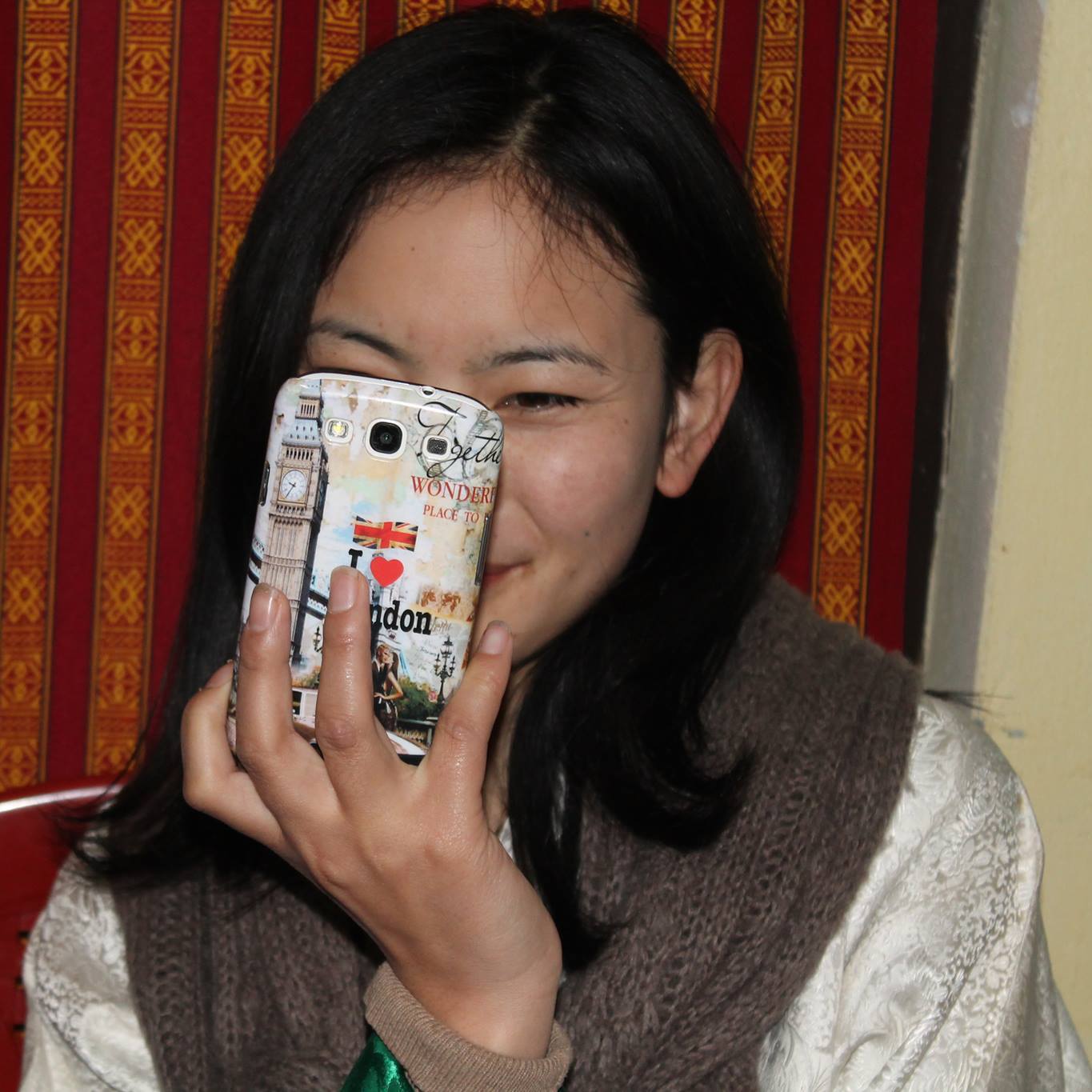
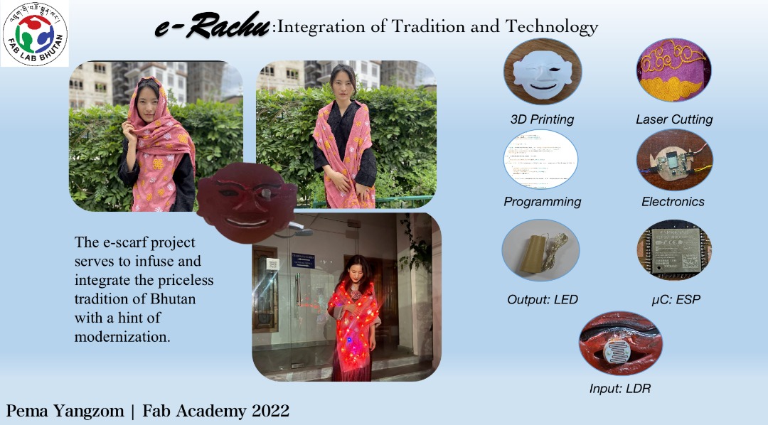
I have always had a fascination with how long our tradition has survived over the course of time. From the intricate designs of the traditional dresses to the way different colored scarfs existed. However, in the current era, the need to combine these dresses with the ever advancing technology is a necessity. Even though I have had little experience with electronics, I wanted to take my experience to another level by integrating the traditional scarf (rachu) with some basic electronics such as a sensor and LED lights. The e-rachu is an electronic scarf that has been designed to respond to the intensity of light and act accordingly. For very dim light, it flickers fast and turns on. Whereas if there is bright light, the scarf turns on and lights up brightly.
A Wearable Electronic Scarf With BroochFor the final project, I wanted to do something fun with respect to the traditional man’s ceremonial scarf called kabney.
Here are a few fun facts while visiting dzongs or government offices which have the national flag. Bhutanese will wear the national costume with ceremonial scarves.
- Men will wear a silk scarf called a kabney from left shoulder to the hip.
- The rank of the bearer will determine the colour of kabney
- The commoners will wear a white kabney
- If you happen to visit the sacred places without Kabney, you can use a rope and wear it like a kabney to enter these places.
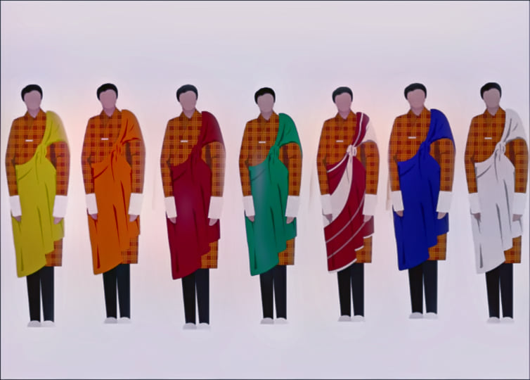
Image borrowed from Daily Bhutan (check out their beautiful illustrations here ),cropped the images and edited using PicsArt image editor.
WhyOne of the main motive behind the selection of this particular project was to integrate technology with traction and have fun while learning. On top of that I wanted to experiment with things.
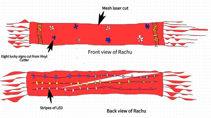
Ideas- By using the laser mesh cutting, cut the polyester fabric
- Laser cut the eight lucky signs and stick/sew it to the scarf
- Integrate the scarf with LEDs all over. I want to use stripe LEDs for my project
- 3D Scan a traditional mask and then make it into a brooch. The mark will serve as a controller case that has the controller and sensors inside
- This scarf can be used two in one. One a ceremonial scarf for man and also as a scarf during chilly days. With a lil bit of dazzle!
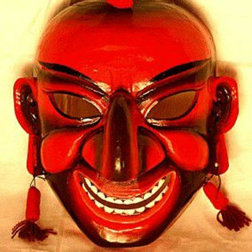 Picture of Atsara
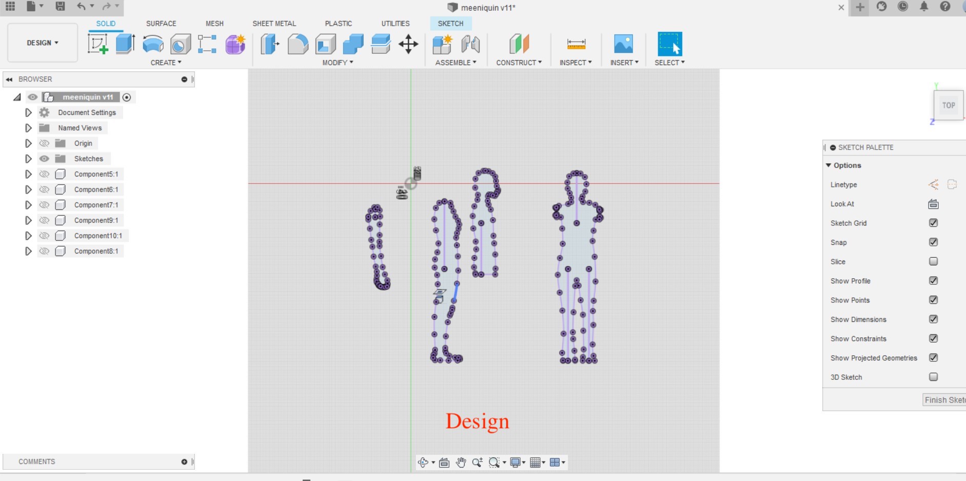
Project Sketch
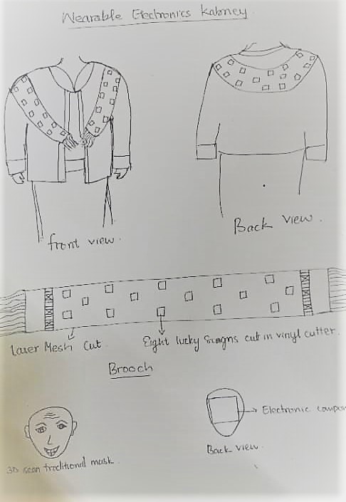
The above sketches were made using sketchpad. Besides the mans ceremonial scarf, I also have an idea to work on womens ceremonial scarf, "Rachu”.
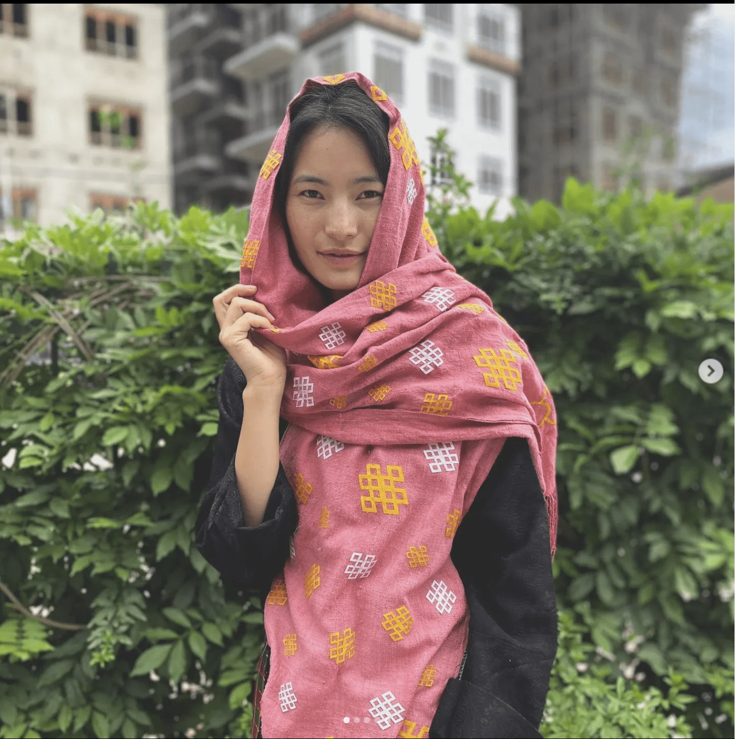
Fun Facts- A Rachu, a long scarf, is worn by females as a mark of respect while attending formal gatherings or visiting temples.
- It is worn just over the Toego and goes well with the overall outfit.
- It is usually red in colour with different patterns and designs.
- The rank of the bearer will determine the colour of kabney or rachu that he or she wears.
- The females will wear colourful rachu with intricate design.
If you happen to visit a Dzong in white colored shoes or in your sneakers, you will either have to walk barefoot from the main entrance or go home. Sharing form my personal experience.LOL!!! Always wear formal shoes but not in white color.
IdeasThe idea is the same thing as that of the mans ceremonial scarf but this one will have lots of color and pattern. Instead of a white fabric I will use red fabric (dyed using natural dyes) for the main scarf and use different colors for the eight lucky signs. I will be cutting the Eight Lucky Sign patterns using laser cutter.
What will it do?With the help of LED, when you put the contoller on, the scarf will give out a really bright glow based on the intensity of light. If the light intensity is less, the LDR sensor will detect it and then respond accordingly to the programming embedded in it.
Who will use it?Though I have not thought of a target audience yet, I plan to disseminate the product with the use of social media and find interested people. On top of that, I plan to wear the arch during my graduation.
Project Description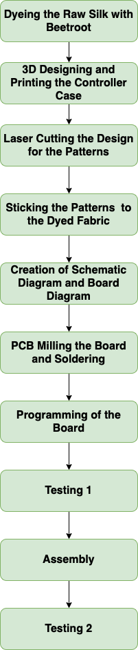 Flow Chart of Work Don
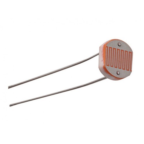
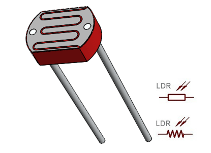
Input
For the final project, the input that I will be using is an sensor called LDR. Photoresistors, also known as light dependent resistors (LDR), are light sensitive devices most often used to indicate the presence or absence of light, or to measure the light intensity. These devices are used in situations where it is necessary to indicate the existence and absence of light. These resistors are used as light sensors, and their main applications involve alarm clocks, street lamps, light intensity meters, and burglar alarm circuits. Though there were alternatives such as push buttons, the reason I Chose the sensor is since it can triggered without touching it. The other reasons include:
- It will last longer than switches or buttons. Touching or pushing a button repeatedly adds wear and tear faster than the sensor. It is important for a product to function consistently for a longer period of time.
- It acts as a preventive measure for the spread of COVID or other viruses. It will be immune to viruses and diseases. Not only will it help in the current situation, but it can also help to prevent numerous skin as well as other transmittable diseases.
Controller
For the controller I used the esp32-wroom-32. Since the project need not be applied in a bigger real field, it does not require any other changes. The LDR senses the intensity of the light and then sends the message to the controller. The controller has all the required code and is the main element of the project. The program embedded in it, helps the LED respond based on the intensity of light (dim, no light, very less light, lots of light).
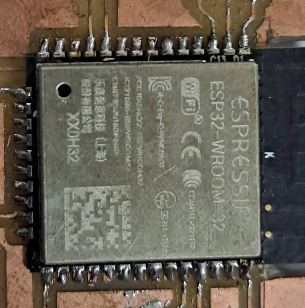 Picture of ESP
Output
For the output I have used strips of LED. Though the initial idea was to use Neopixel, due to it's unavailability in the market I decided to use the strip of LED. LED strip lights are innovative and versatile lighting options. There are numerous variants and exceptions, but they all share the following characteristics:
- Several individual LED emitters are positioned on a limited, flexible circuitboard.
- Use low-voltage direct current power.
- Are available in a variety of fixed or variable colouring and brightness options.
- Ships in a lengthy reel (typically 16 feet / 5 meters), is cut to length, and comes with double-sided adhesive for mounting.
The LED pixels act as indicators that show the output based on what is sensed by the LDR sensor. The LED flashes and brightens in response to the intensity of light sensed by the sensor. It has been hand stitched into the fabric
 LED
LEDMaterials Used
- Raw Silk
- Polyester Fabric. I am planning to dye the scarf with natural colors. So the colors of the polyester fabrics must be something that stands out. White, Yellow, Green are my choices for now
- Stripe Clothing LEDs
- 5V Power Supply
- ESP 32
- Electronic Components for Controller (Microcontroller)
- Sensors (LDR)
- 2 Resistors
- 2 Capacitor
- 2 Regulators
- 1 Switch
- 1 MOSFET
- 1 Slider Switch
What does it do?
The project is focused mainly on combining tradition with technology. The priority is given in making sure that is a balance between the beauty of the traditional fabric and the modern touch of technology. However, it can also serve as a source of illumination when women go in dark areas with no street light etc. The project is to integrate the evergreen culture of Bhutan with the ever-growing technology.
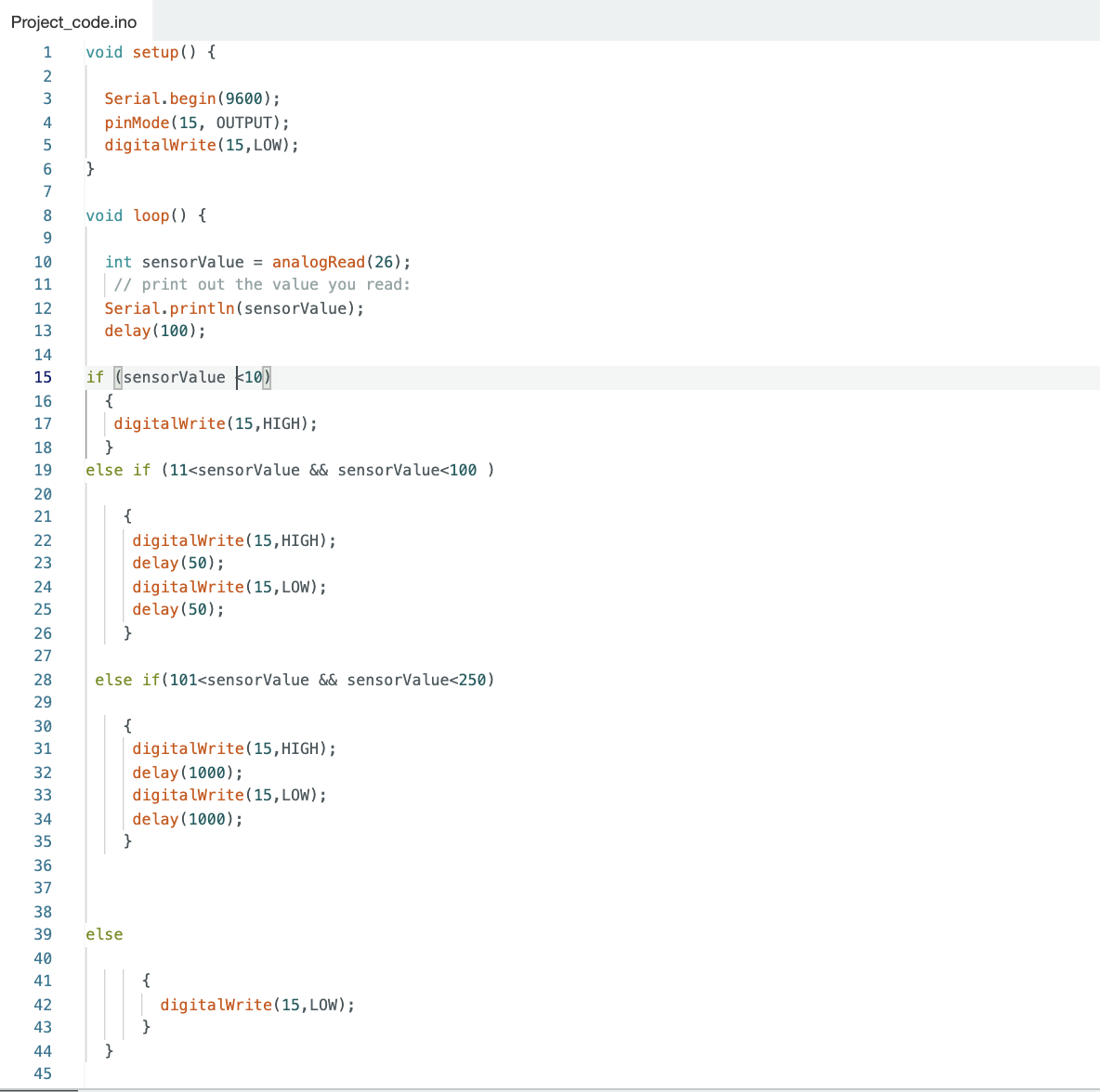
What did you design?The design was kept as simple as possible. Goal while designing the product was to bring down the cost as much as possible. The raw silk that has been dyed is recycled. The scarf has been stitched with stripes of LED. The functionality of the scarf is such that when the LDR senses light value less than 10, the LED lights up brightly and flickers intensely, for sensor value between 11 to 100 it will light up bright and flicker slowly, for sensor value more than 101 it doesn’t light up. All of the required functionalities work properly with no error.
Where did they come from? How much did it cost?Most of the components required for my project was available in the lab’s inventory. Some of the purchases made were LED strip and design fabrics.
| Sl No. | Items | Quantity | Source | Approx Price |
|---|---|---|---|---|
| 1 | ESP32-WROOM-32 | 1 | Fab Inventory | - |
| 2 | LDR Sensor | 1 | Fab Inventory | - |
| 3 | LED Strip | 3 | Amazon.in | Nu.750 |
| 4 | Resistors | 2 | Fab Inventory | - |
| 5 | Capacitors | 2 | Fab Inventory | - |
| 6 | Regulators | 2 | Fab Inventory | - |
| 7 | Switch | 1 | Fab Inventory | - |
| 8 | Raw Silk | 1 | Local | Recycled |
| 9 | MOSFET | 1 | Fab Inventory | - |
| 10 | Slider Switch | 1 | Fab Inventory | - |
| 11 | Jumpers | As Per Requirement | Fab Inventory | - |
| 12 | Fabric for Design | 2 | Fab Inventory | Nu.200 |
| 13 | Miscellaneous | - | - | Nu.500 |
What parts and Systems were made?
- Fabrication of the Controller Boards of ESP32-wroom
- 3D designed the controller case using Fusion and printed it
- Integration of the input (LDR sensor) with the output (LED)
- One board in the controller case that looks after the overall functionality
| Sl No. | Particular | Process |
|---|---|---|
| 1 | Fabrication of the main controller board through the ESP32-WROOM-32 | PCB Milling Machine |
| 2 | Coloring the Raw Silk | Dyeing with beetroot and other natural dyes |
| 3 | Cutting the Fabric Design | Laser Cutter was utilised |
| 4 | Printing of Controller Case | 3D Printer |
| 5 | Soldering of the components and making the circuit | Soldering and Wiring |
What Questions were Answered?
My project is based on what is required the most. With my project system working and utilized by required people it will help people in my country understand that technology can help with beautification our tradition and not it's degradation. It can also serve as illumination in places where there is an absence of street lights. One of the ways it can be applied in the real world is by being an indicator that there is someone walking down a road and preventing unnecessary accidents.
What Worked? What didn't?Everything that was initially planned is functioning well. One thing that I want to add is a rechargeable power supply. It is inconvenient to use the 5V power supply while traveling long distances.
How was it evaluated?The evaluation was done based on how well it functioned and how good it looked. Though I have no intention of producing it in a large quantity, based on how well it works I might change my thoughts.
What are it's implications?As the project involves textile and tradition, I am planning to approach the Royal Textile Musuem. The musuem show cases different wearables our country has produced over the years. My scarf will be a unique and beautiful addition to the musuem. My other plan is to give it to the orgranizations in our country that are concerned with fashion.
Fabrication Process
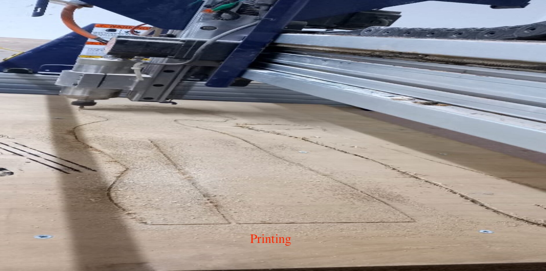
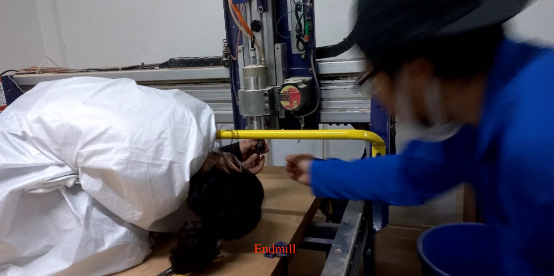
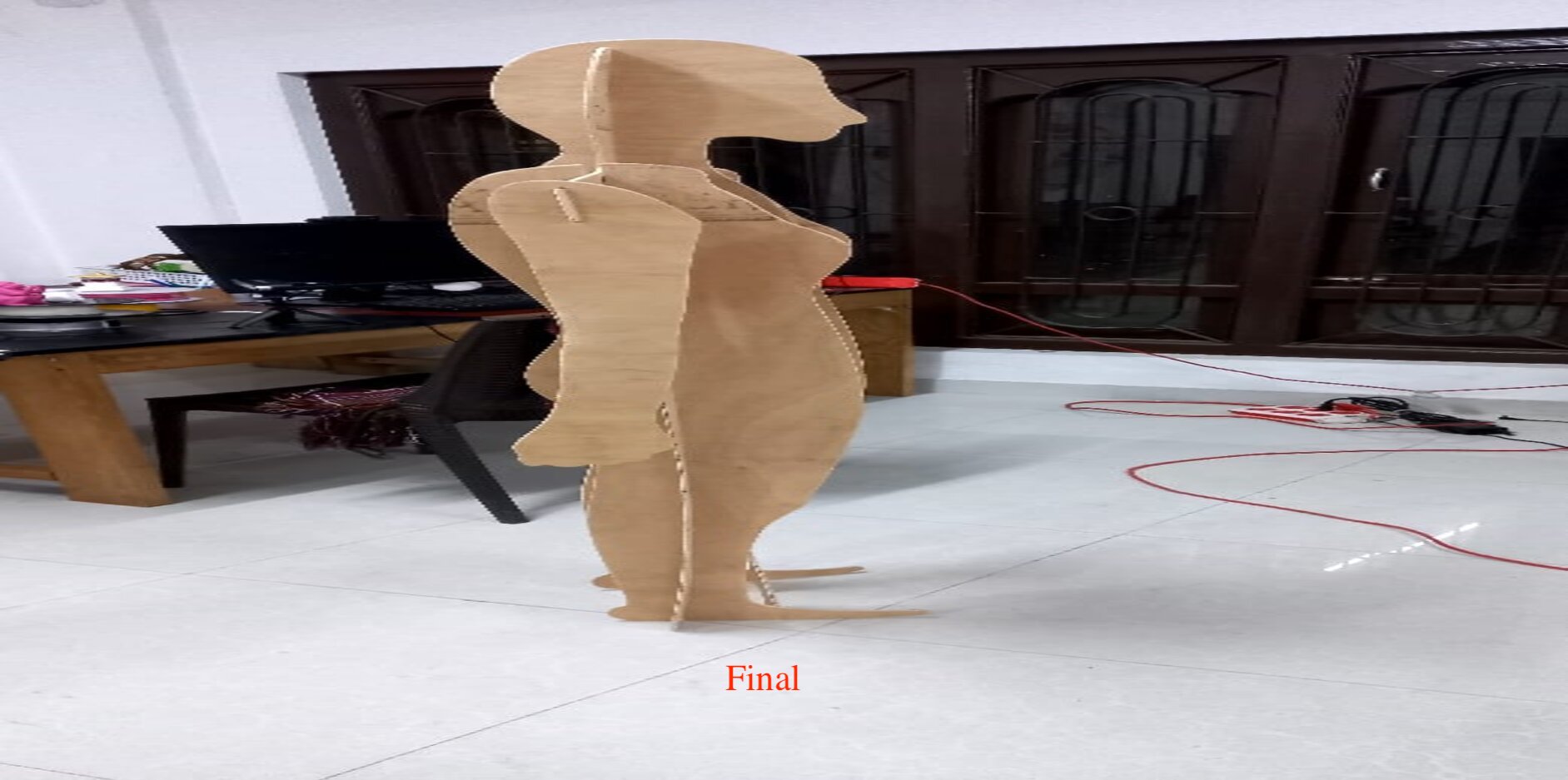
Mannequin Fabrication Using CNCTo make a model to display my scarf, I made a Mannequin using CNC. This was done during the make something big week.
Design of Controller Case and Printing
I used a 3D printer to make the controller case in order to store all the electronic components. The 3D printed product is shown below
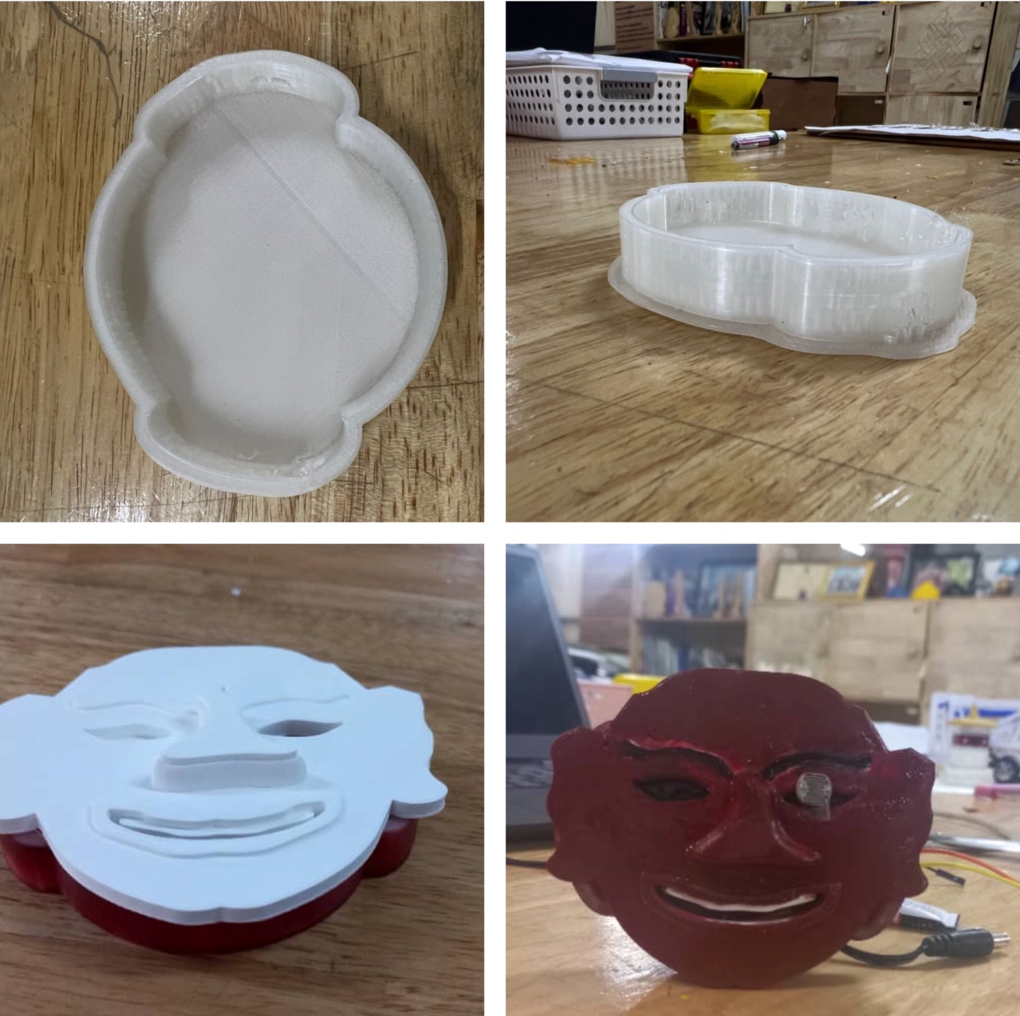
Printing Process is shown in the video below
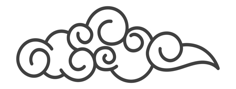
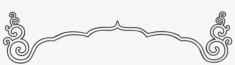
Design for the Scarf Cut Using Laser CutterUsing the laser cutting machine, I cut the design for my scarf. The design was made using CorelDraw. Using two different colors of fabric, I made the patterns.
The designs were made using inkscape and coreldraw. The images shown below are the designs that were made using the respective softwares. These are designs that can be seen in most Bhutanese architecture or textile. It represents a part of our culture.


The video shown below displays the laser cutter, fabricating the design patterns
The image below shows the output after laser cutting the patterns. This was stuck on the raw silk (scarf) using glue.
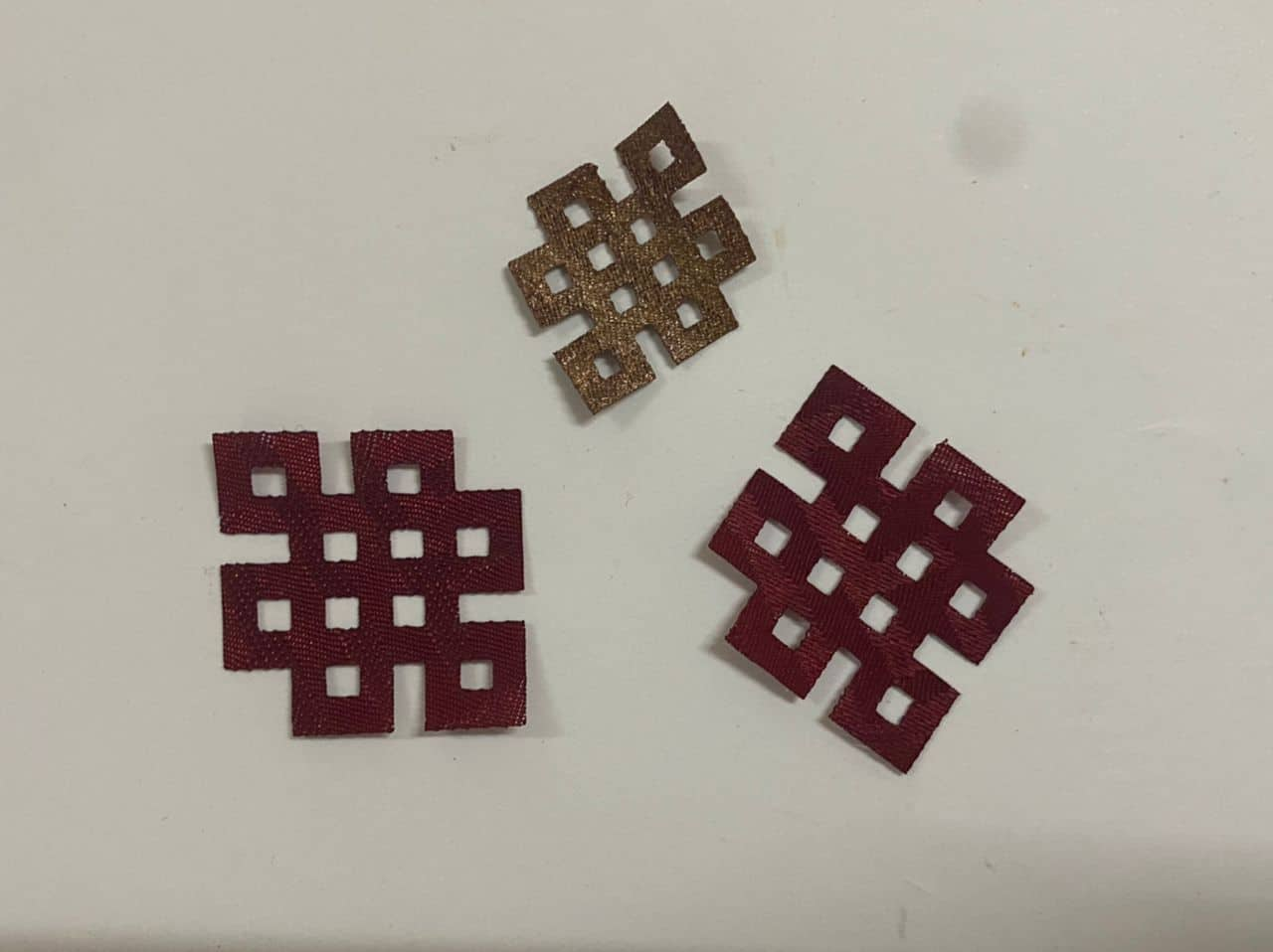
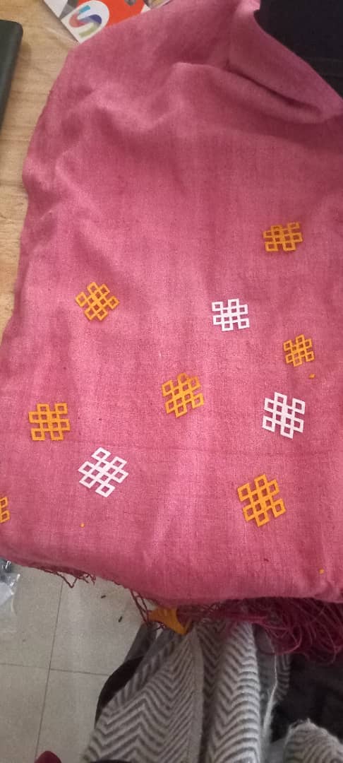
The following video shows how the patterns were stuck into the raw silk using glue. Though it was a tiring process, I was motivated enough and didn't lose hope in between
Board Design
The picture shown below shows the design of my board. With the help of some colleagues here and the addition of schematic design, I milled the board. Through the board, all integration was done.
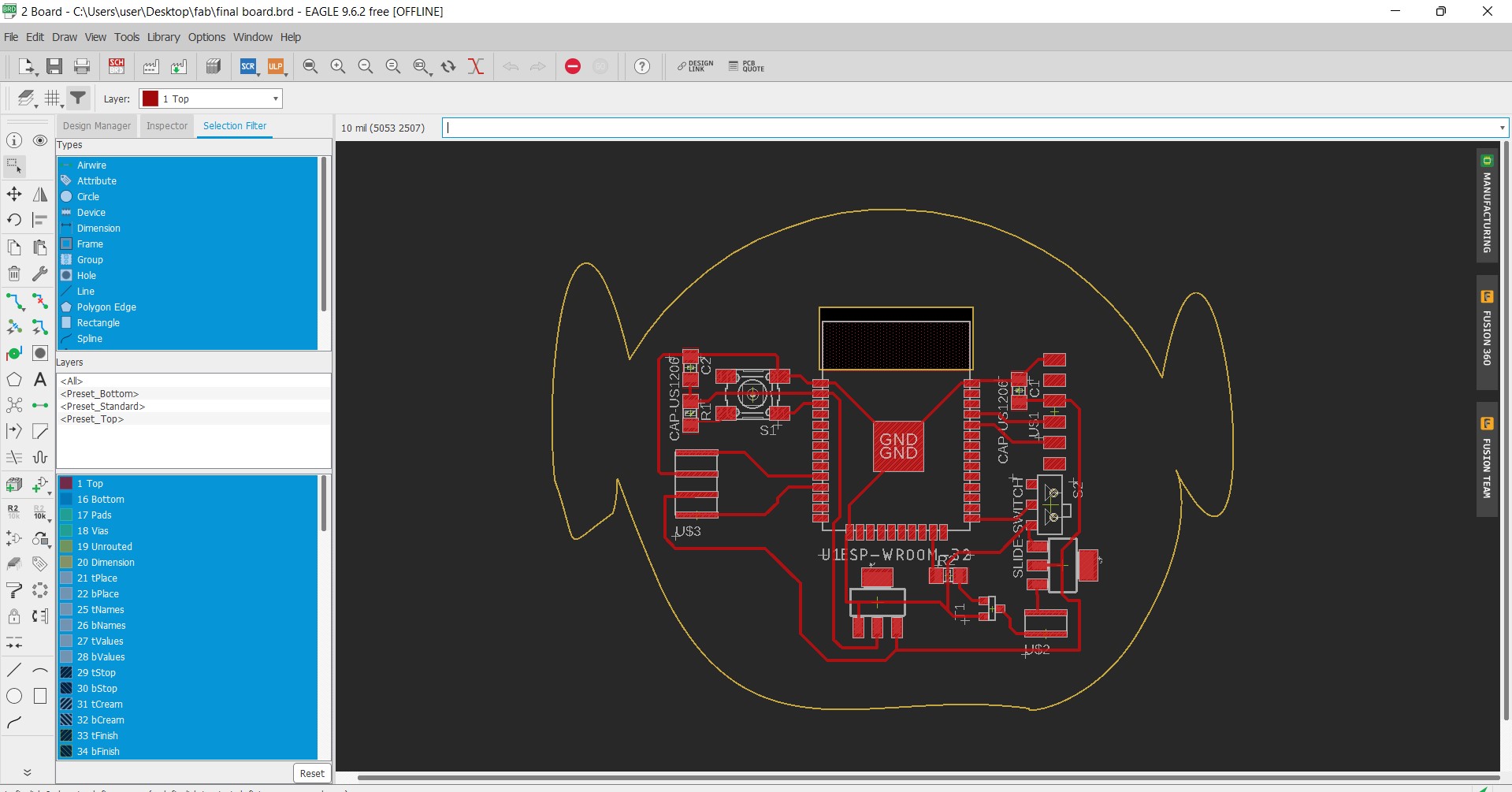
This is the my final project board that was milled using the PCB milling machine. One of the tasks that was the hardest to carry out was of the soldering work. Other than that, it was pretty much doable
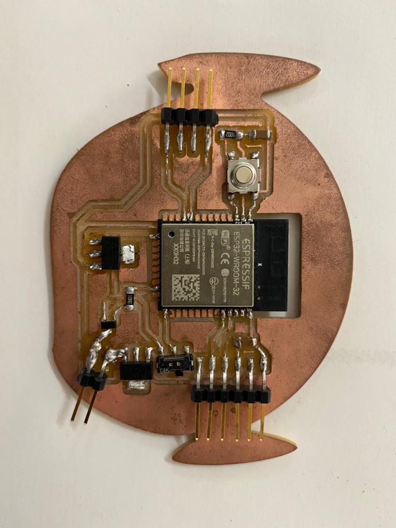
The video though short shows how the board was milled.
Electronics and Programming
To program my ESP board, I used Arduino as the FTDI interface. According to one of the Fab Academy students, the ESP32 doesn't really require a programmer. Instead, an FTDI programmer will be used. The following procedures could be used to convert an Arduino to an FTDI:
- Adruino EN and GND have been shortened.
- Inserting a new program into the Arduino
- Taking the IC out of the Arduino.
Out of the above mentioned procedures, the best one was to load the blank program into the Adruino.
void setup(){
pinMode(0,INPUT);
pinMode(1,INPUT);
}
void loop(){
}
The above shown arduino code enables the RX and TX pin of the adruino to act as output pins. Once you are done coding, load the code into the adruino that you are going to utilize in order to use it as a FTDI.
Light Intensity Detection InterfaceAfter successfully testing the various input and output elements using my final project board, it was time to try something a little more complicated. One of my project's primary functions is to detect the intensity of light and then respond accordingly. I wanted to put that to the test while Suhas was still in Bhutan.For the light intensity detection I used an LDR sensor. As mentioned above to counter the problems of using a button I used an LDR sensor. In different intensity of light, the code embedded in the microcontroller makes the LED flicker and glow in different ways. The user can easily idenity the intensity of light through the output (LED). The only time the LED does not light up or flicker is when the intensity of light is high. The entire project is powered by a 5v power supply.
The code is as follows:
System Integration
Once the testing of individual electronic components was completed, it was time to assemble all the components together. One of the tasks while integrating all the components together was to put the electronic systems into the controller case and doing all the connections.
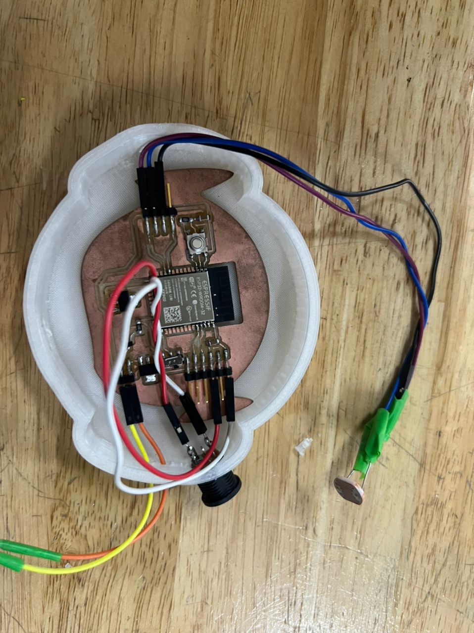
The microcontroller was placed inside the controller case along with the MOSFET, LDR and other components. The main goal of using the 3D printed controller case was to encapsulate as much of the connections as possible whislt showing our beautiful culture. Then the connection with the LED bulbs was made stronger to prevent any sort of issues if the components were dropped.
Overall Assembly and Fabrication Video
Final Product
Presentation.png.
Presentation.mp4.
Thank you Fab ACADEMY
Files
Source code3D Design
Laser cutting
Laser cutting 1